
From schematic to tested board.
PCB design, firmware, software and small-batch assembly — designed, built and verified on our own line in Clayton, North Carolina, serving Raleigh and the Triangle.
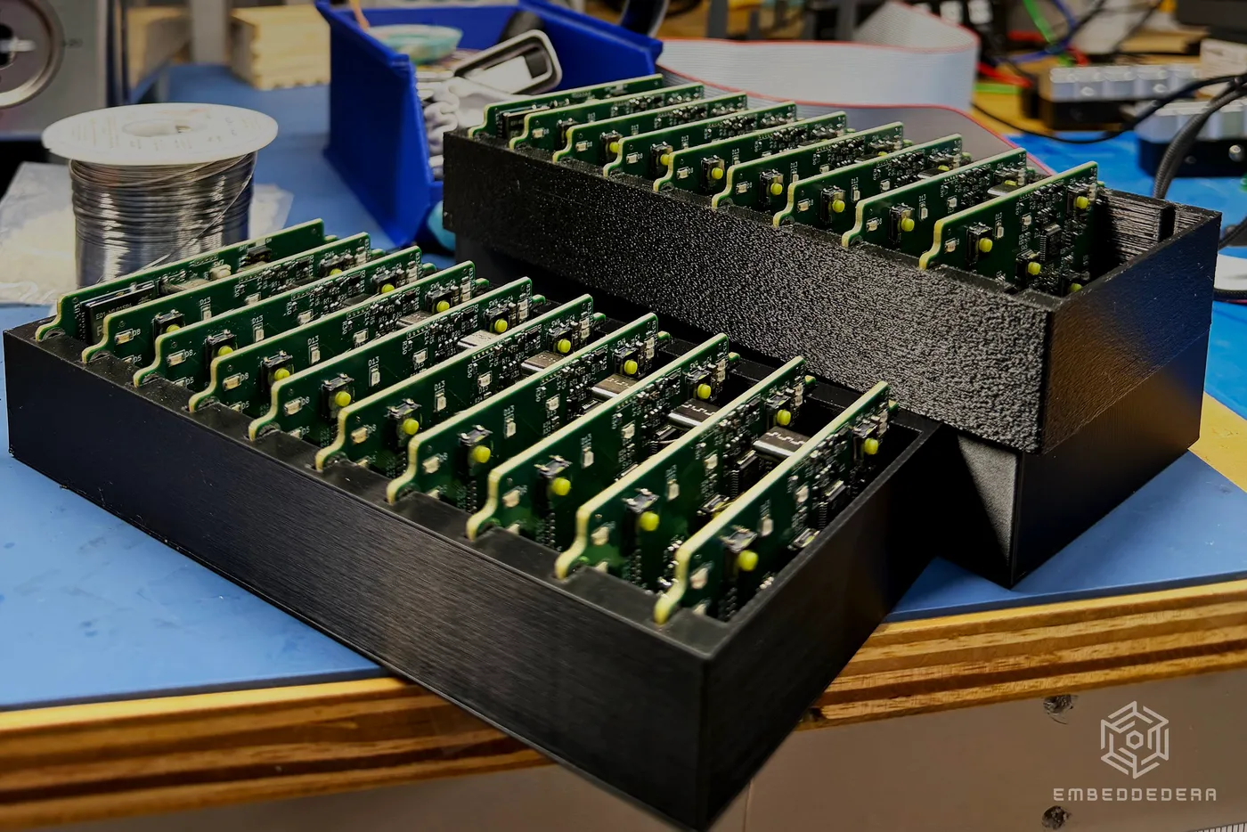
Your outsourced R&D department.
No hardware team? We take an idea through feasibility, proof of concept, prototypes and a pilot run — one engineer, one point of contact, everything built and tested in Clayton, NC, just outside Raleigh.
What we do
Five things we do end to end.
- Design R&D and product development, PCB layout, schematic, BOM & DFM, membrane switch overlays, mechanical CAD and drawings, enclosures and fixtures.
- Firmware Bare-metal and RTOS firmware across STM32, ESP32, Nordic nRF, Microchip, TI, and Arduino-compatible parts — UART, RS-232, RS-485, I²C, SPI, CAN, LIN, USB, Ethernet, BLE, Wi‑Fi, and sub-GHz/2.4 GHz radio, bootloaders and over-the-air updates.
- Software Companion apps for iOS and Android, web apps and browser device tools, desktop utilities for macOS, Linux, and Windows, dashboards.
- Build and test Small-batch SMT assembly, automated test fixtures and 100% testing.
- Redesign Obsolete and end-of-life parts, firmware porting, reverse engineering of legacy boards.
Keep shipping when a part goes end-of-life.
We find the replacement, redesign the board around it, and port the firmware if a new chip needs a new framework — so a discontinued component doesn't discontinue your product.
Built and tested in house
Our own assembly line
Parts down to 0402, with QFN and BGA packages up to 18 × 18 mm, on boards up to 8.0 × 10.5 in (200 × 260 mm). Up to 52 unique reels loaded at once, for dense, component-heavy boards in a single pass. Dual-camera vision verifies every placement to ±0.02 mm before reflow, run lead-free and RoHS-compliant. It’s a real production line, sized for the pace of prototypes and small-batch runs.
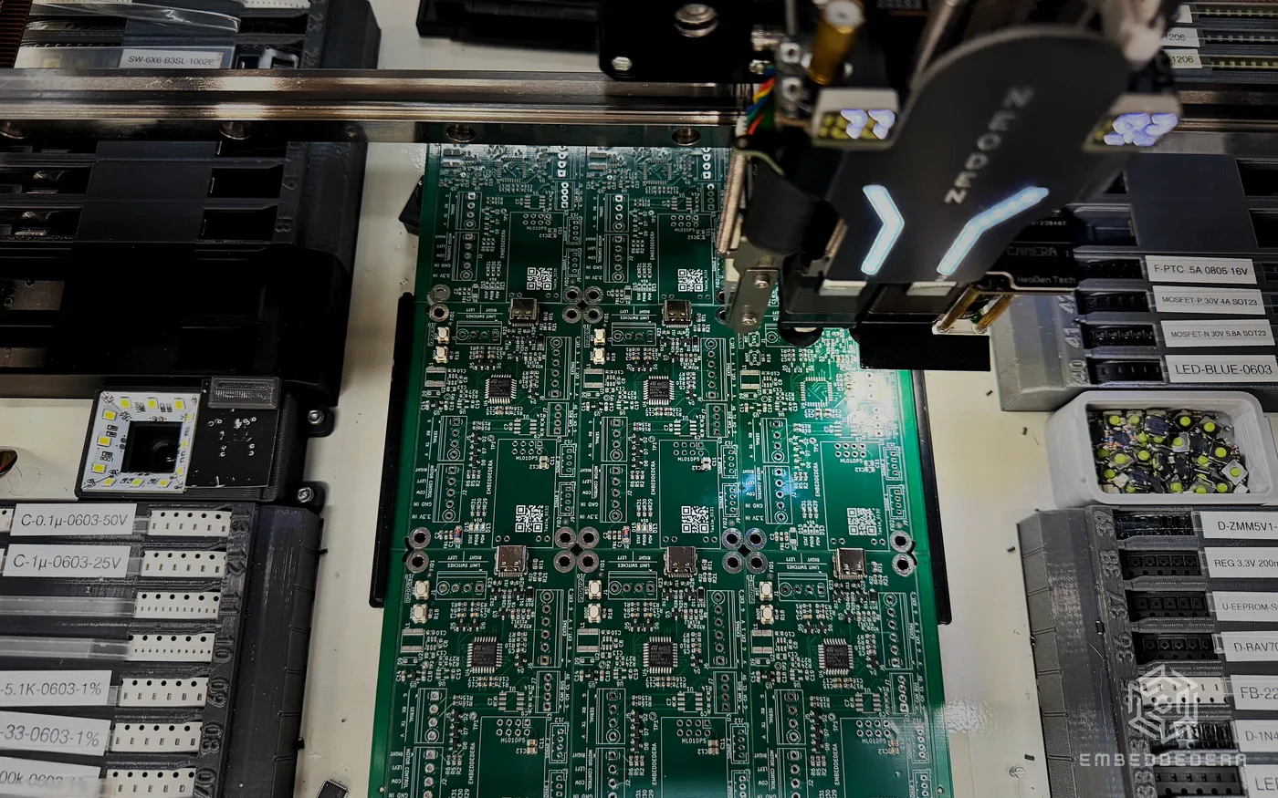
100% testing, logged and serialized
Every board we build runs a fixture-specific automated test — power, current, and sleep-current limits checked, and every indicator verified by camera instead of an operator’s eye. Results are logged against that unit’s serial number, so there’s a per-unit record behind it. The same fixtures and station software are also something we design for a client to run on their own line.
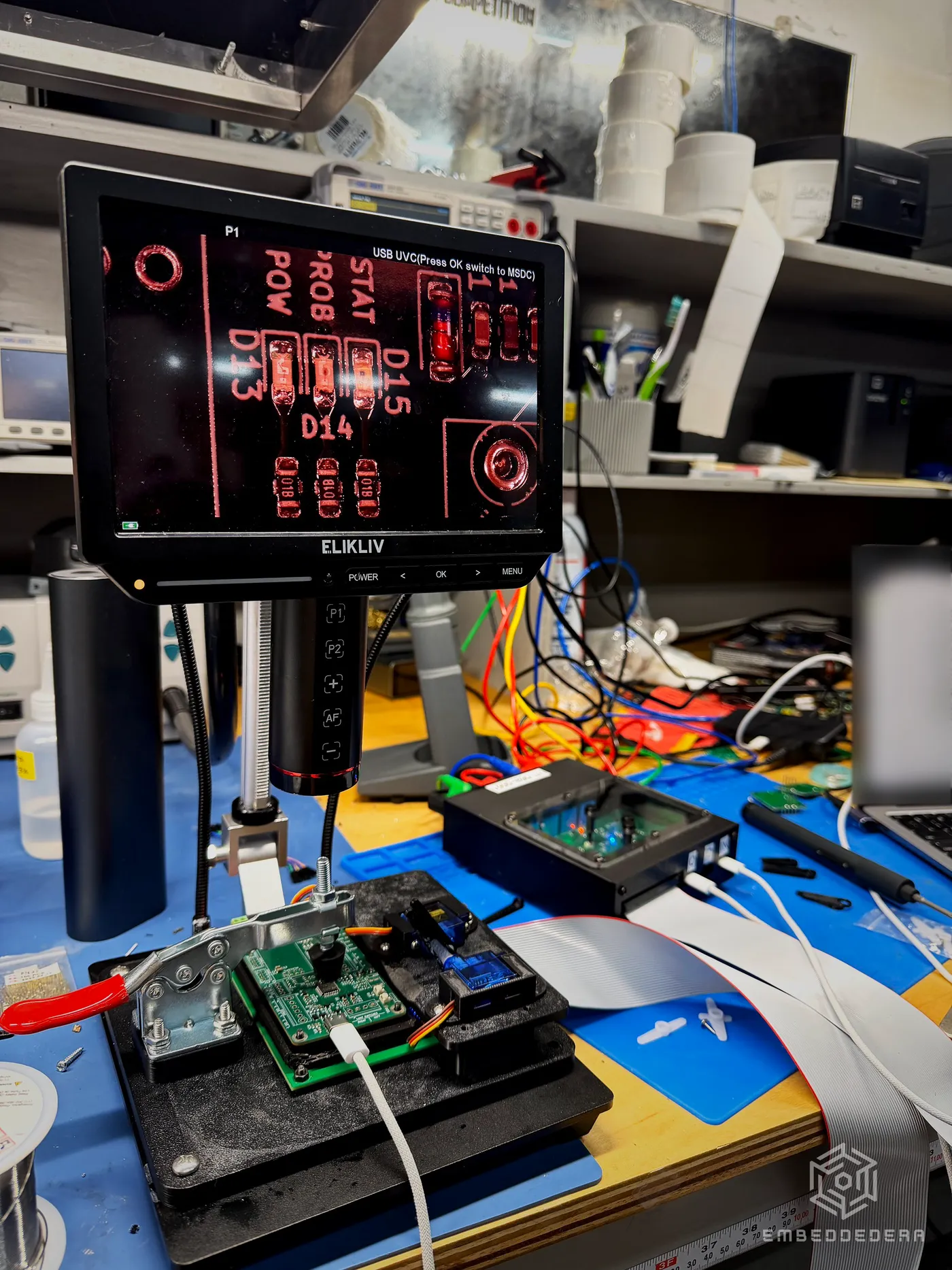
Enclosures and fixtures, made here
Enclosures, panels, and fixtures come off our own laser cutter and multi-material 3D printers, not a separate shop. Everything is drawn in CAD against the actual board and its connectors, so cutouts and standoffs line up the first time. Every part starts as a SolidWorks model, with shop-ready technical drawings and tolerances the moment it needs to leave the building. Fit is checked on a real printed or cut part before anything goes to volume.
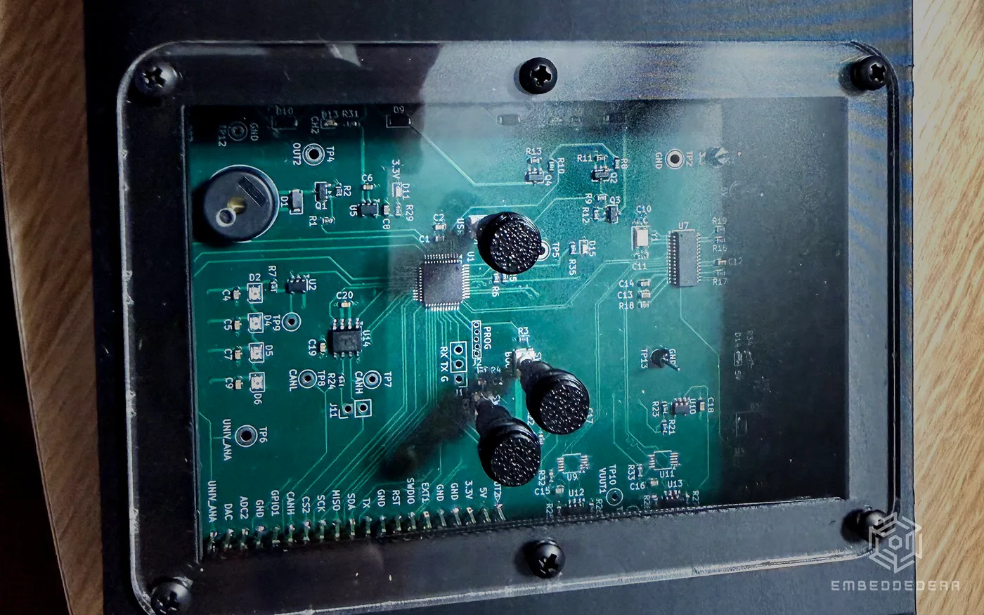
Five steps, one point of contact
- 01 Scope A written scope of what’s being built.
- 02 Quote A fixed quote.
- 03 Schematic & layout A reviewable schematic and layout, before anything is ordered.
- 04 Prototype & test Assembled, tested prototypes with a test report.
- 05 Hand-off Production files, a BOM, a firmware release, and a hand-off call.
Let's talk about your board.
Clayton, North Carolina · [email protected]